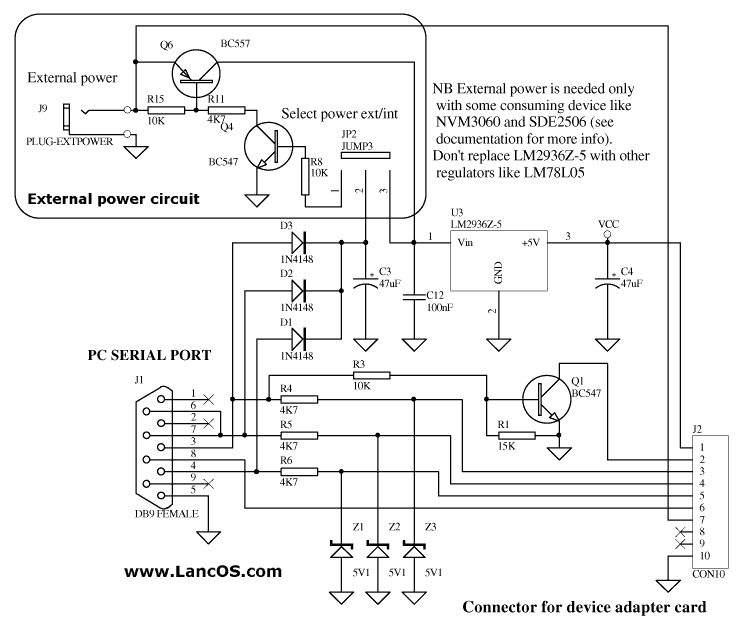
Spi Serial Flash Programmer Schematic Drawings
The TMS570LS12x Hercules Development Kit (HDK) is ideal for evaluating and starting development with the Hercules platform of safety microcontrollers. The kit is comprised of a development board, a DC power supply, a mini-B USB cable, and Ethernet cable and a software installation DVD. The development board features an on board XDS100v2 JTAG emulator along with access to several key communication and peripheral interfaces.

 Serial Peripheral Interface (SPI) is an interface bus commonly used to send data between microcontrollers and small peripherals such as shift registers, sensors, and SD cards. It uses separate clock and data lines, along with a select line to choose the device you wish to talk to.
The HDK features: • 337p BGA TMS570LS1227 MCU, on board • On Board USB XDS100v2 JTAG • On Board SCI to USB Serial • 20pin ARM and MIPI JTAG connectors • 8 White NHET LEDs • 8MB SDRAM (EMIF) • Ambient light and temp sensor • 2 CAN transceivers • 1 RJ-45 ethernet port • 1 Micro SD card slot (SPI mode) More information specific to the TMS570LS12x Hercules MCU family can be found on the.
Designing with discrete flash is 1/10th the cost, uses a much smaller form factor, and requires significantly less specialized hardware than using SD flash cards. This Instructable will show you how to add 1MB of discrete external flash memory to your microcontroller project with what I believe to be the least amount of effort possible. This is also a follow-on to my other two data-logging Instructables (an and a ) that explains how to download the data from the logger flash memory using age-old TTY command line applications found in Linux. Motivation Whenever I'm building an Atmel ATMega or Arduino project and I need to record data, I almost always reach for a single rather than an SD flash subsystem. Many reasons exist to choose a discrete flash chip over an SD subsystem, and vice versa, and you'll need to consider these tradeoffs for your design. The list below contains a few tradeoffs I think about when I need to decide if I want to use a single 8-pin DIP chip or a full-on SD solution: Hardware Complexity (Choose: Discrete) One way to add SD flash to an Arduino system is to use a shield, such as (three 'e's) I bought at my local Radio Shack for $15. While shields provide convenience for prototyping, the final production assembly might not have the budget or the space to include SD hardware.
An 8-pin DIP package of a discrete flash chip is much easier to drop on a protoboard than an SD shield, assuming your development board even supports a shield. Software Complexity (Choose: Discrete) The SD flash subsystem commonly relies on. While the devices are an SPI interface, it makes sense to use FAT since any PC/MAC can then read this card. These libraries are large and can take up precious EEPROM space on smaller embedded controllers. Compatibility and integration into your build environment may require significant debug.
The software required to drive a discrete flash chip with an SPI interface is trivial and very small, as you will soon see. Maybe this says more about me than the SDFat libraries, but I find them cumbersome to work with. Capacity & Portability (Choose: SD) SD flash wins big here, simply pop in a larger capacity SD card into the existing design with no modifications. Discrete SPI flash has lower density limits in the 8-pin DIP format. The SDFat library means any PC/MAC can read the files on the card. Cost (Choose: Discrete) SD cards range in price dramatically, and with an SD flash shield, can set you back $20-$30.
WinBond 1MB chips cost about $2 from Mouser or Digikey. Power (Choose: Discrete) Energy requirements of flash depend on the manufacturer, production lot, device density, and process technology. SD cards are typically higher leakage power due to the higher densities, and higher dynamic power due to the higher access speeds. The WinBond chips I focus on in this Instructable require very little power, 6uW standby, 60mW page program, and 60mW chip erase. I wasn't able to find power data on the high-end super-fast SD cards, but the write speed is about 100x that of the WinBond. Since dynamic power is proportional to frequency, I can't imagine power would be less. Speed (Choose: SD) I haven't had any need for very fast flash memory write performance, but SD flash comes in many different product SKUs based on speed (mostly due to the demands of digital photography and the use of raw image formats).
The WinBond SPI chips can't really compare: page program speed is 0.7ms for 256 bytes, which translates to 0.360MB/s, which is 100x slower than Team Corp.’s fastest Micro SD cards at ~40MB/s. I suspect they have multiple devices or arrays writing in parallel to achieve those speeds. While this analysis most likely represents my own lazy biases, I find my brand of laziness to be rather prolific. That being said, any one of these vectors may be more important for your project, but my goal here is to call out the tradeoffs, and then illustrate the simplicity of this wonderful flash chip.